OneVariable Newsletter - 2022-01-19
2022-01-19This article was originally featured on the OneVariable Applied Research newsletter. If you'd like to get early access to these reports, you can sign up for the newsletter here. Newsletter emails are sent every Wednesday.
Articles are posted on my blog one week after appearing on the newsletter.
Abstract and Results
The new year continues with more hardware-related distractions.
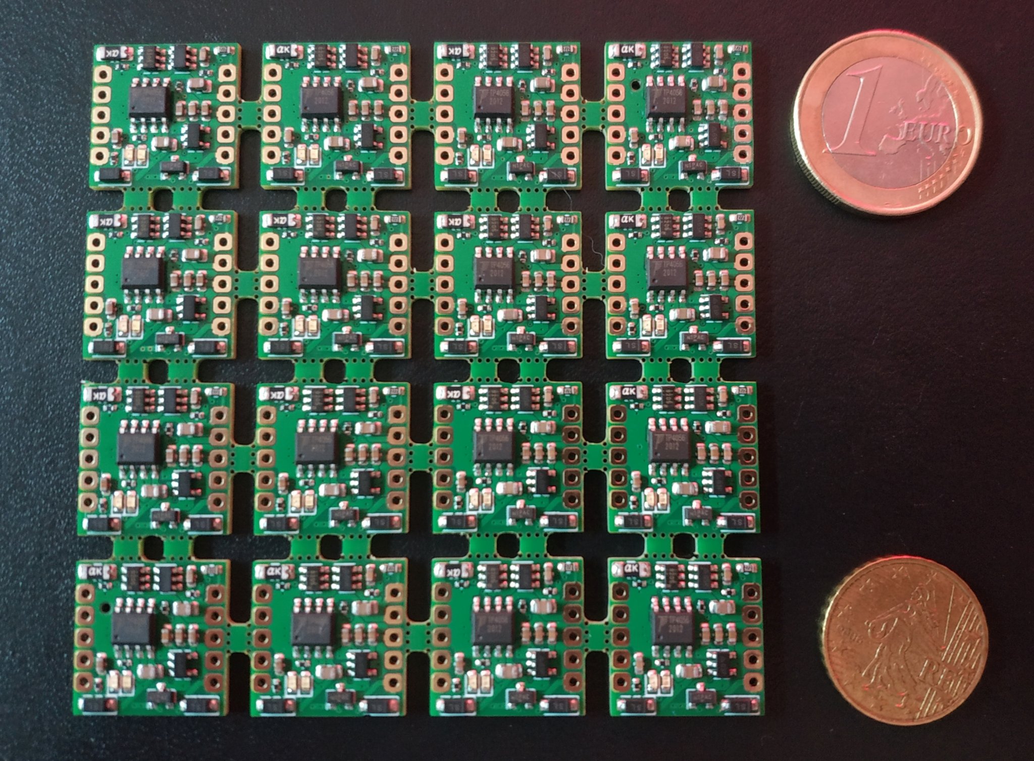
This week, I went back to an old project from about a year ago, my Lipo Stamp hardware, which is a small battery charging, management, and protection PCB. It was designed to handle all of the "battery hard stuff", so I didn't need to design that into every project.
As things go, I didn't end up ever testing or using these stamps at all, so they've been waiting in my drawer to be validated.
Lipo Stamp Panel
I've finally set up a test rig for the stamps, as well as a minimal mechanical keyboard project to use it in.
It's your week to shine, Lipo Stamp!
Background Information
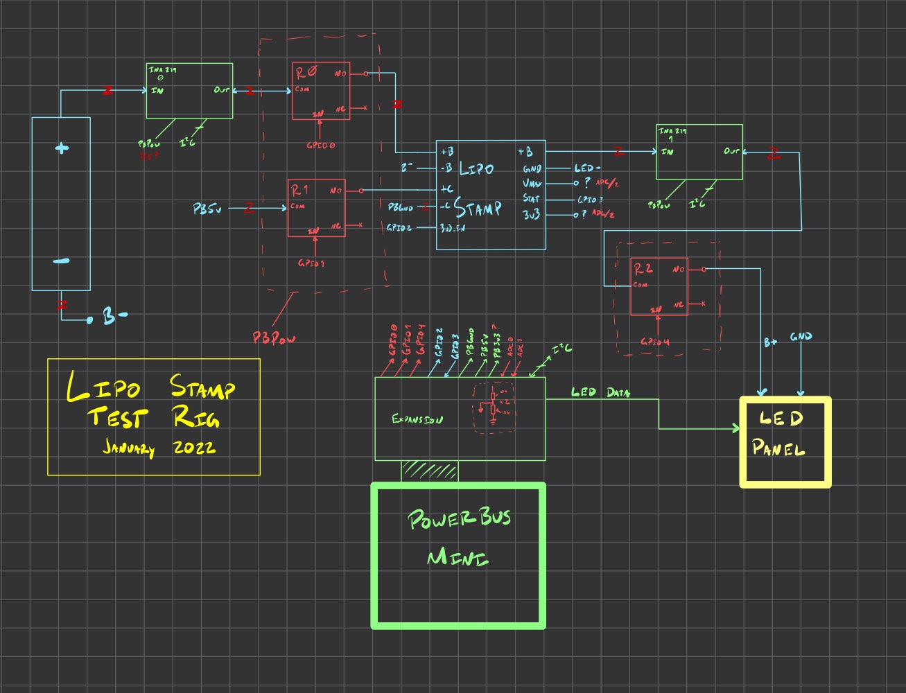
Lipo Stamp Test Rig
In order to test the Lipo Stamps, I wanted to have a test rig that continually charged and discharged the batteries while monitoring the stamp, to make sure that everything was working as expected
Since the 18650 batteries I plan to use are relatively high capacity (3400mAh, at 3.7-4.2v) and the lipo stamp can handle up to 2A of discharge current, this meant being able to charge at the baseline 500mA rate (for 5-6 hours), and discharge at up to 2A (for 1.5-2 hours).
Additionally, I wanted to monitor the charge and discharge rate, as well as verify the protection circuitry worked as expected, with a polyfuse cutting out at >2A discharge, and undervoltage protection kicking in when the battery discharges too far, even at lower currents.
This setup would use:
- A Powerbus Mini to control the behavior
- Relays to switch power
- A pair of Adafruit INA219s for current and voltage measurement
- A 64-LED panel as a programmable load
Lipo Stamp Test Rig Diagram
With this setup, I can run a number of tests, including:
- Connect the battery and charging cables via relay, and monitor the charge rate and voltage
- Disconnect the charging cable, and attach the LED power
- Use the Powerbus to enable different amounts of LEDs, to control a discharge current of zero to three amps, depending on the desired scenario
Based on the diagram, I assembled a test setup. Here's a snapshot, with annotations of each part:
Lipo Stamp Test Rig v1
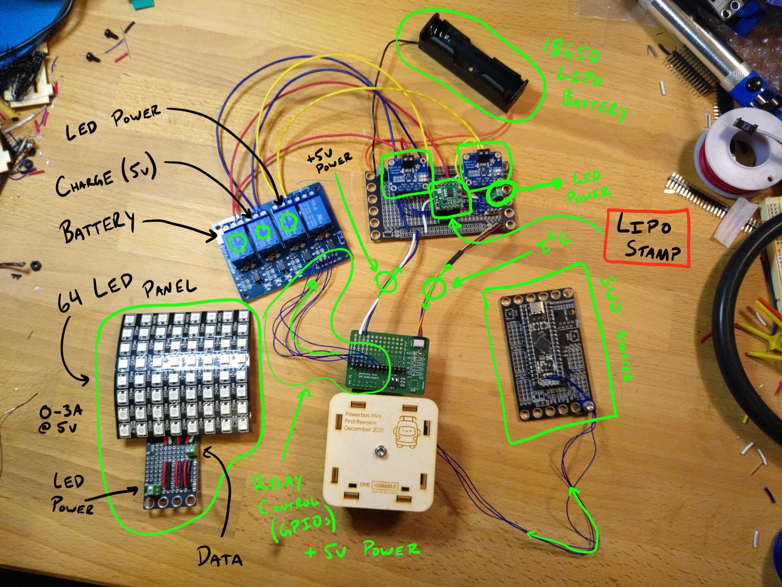
It ended up being a lot of hardware to test a tiny little board! But I should be able to have repeatable tests, and let it run for a couple of days, while only lightly monitoring it (to ensure nothing catches fire unattended).
I've written some basic firmware that can toggle the relays and monitor voltage and current, but I haven't written the full test scenarios yet.
Splitpea Keyboard
Earlier this week, I saw a tweet (and a blog post) describing a super minimal, 34-key keyboard layout. I'm not really a "mechanical keyboard guy", but a couple unrelated ideas clicked together, and I decided this would be a fun project to throw together.
I ended up going with 38 keys (19 on each half) in order to make each half of the keyboard symmetrical. This way I'd only need to design one board, instead of a "left" and "right" hand version.
Splitpea Keyboard Layout
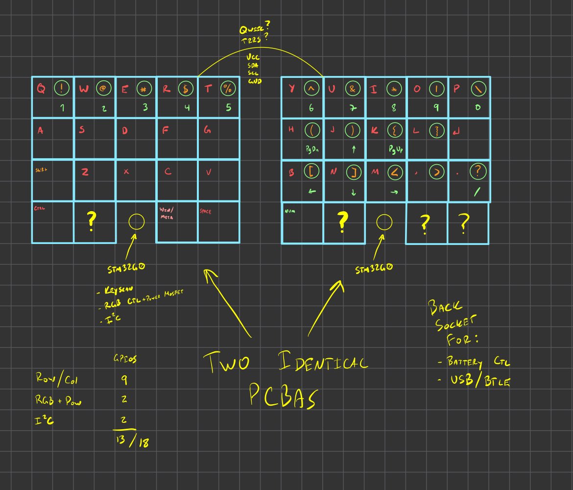
Splitpea Keys - Front and Back
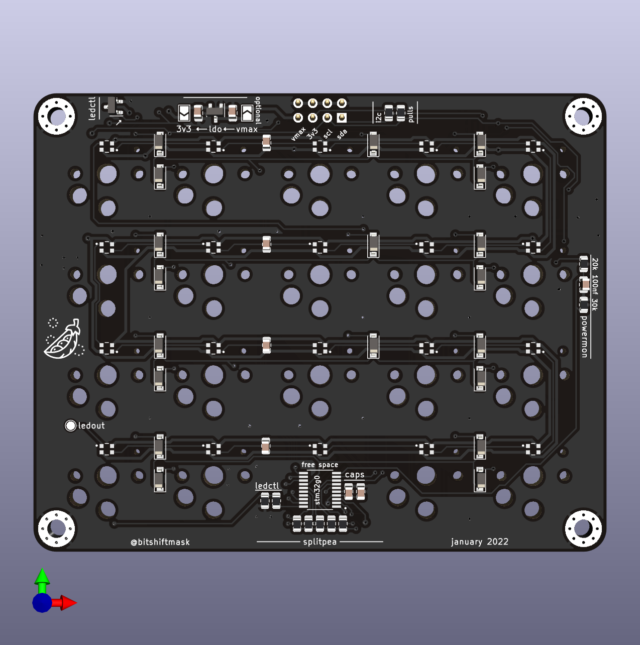
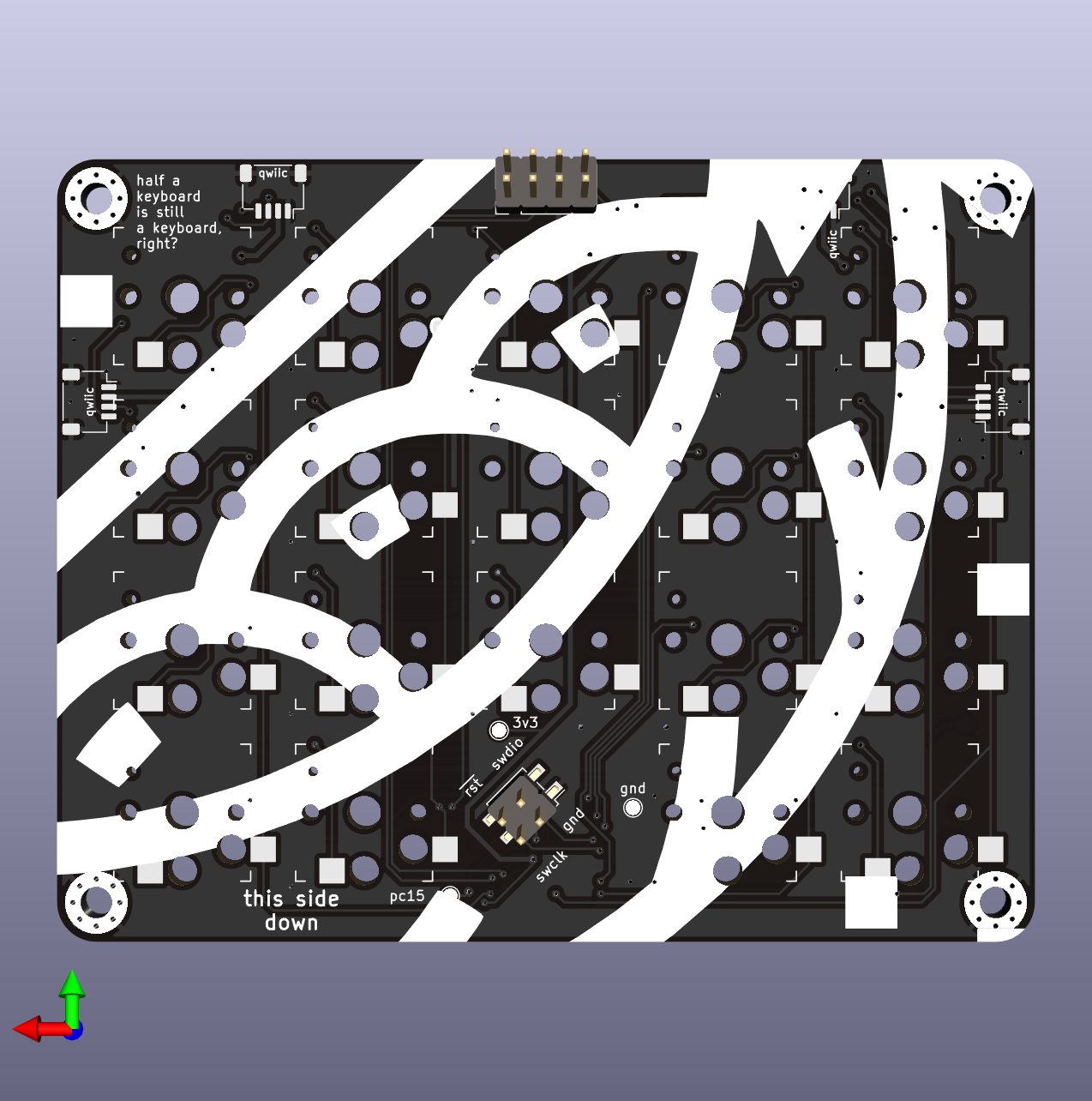
Each half has an STM32G030 in TSSOP-20 form, which gives just enough pins to manage the row/column keyboard matrix, control of the 20 WS2812B-2020 LEDs, and an I2C connection to a "host" microcontroller to communicate with both halves. This part (above) isn't a keyboard, just the "keys" part!
For the "brain", I also designed a "stem" board to go with the Splitpea Keys.
Splitpea Stem - Front and Back
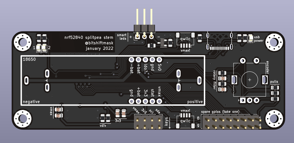
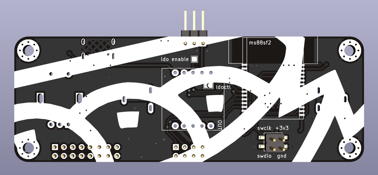
The stem board has the more complex parts on it, including:
- An 18650 cell holder (on PCB), using Through-Hole Metal Clips
- An nRF52840 SOM (the "brains")
- A Rotary Encoder
- A USB-C connector
- Space for the Lipo Stamp
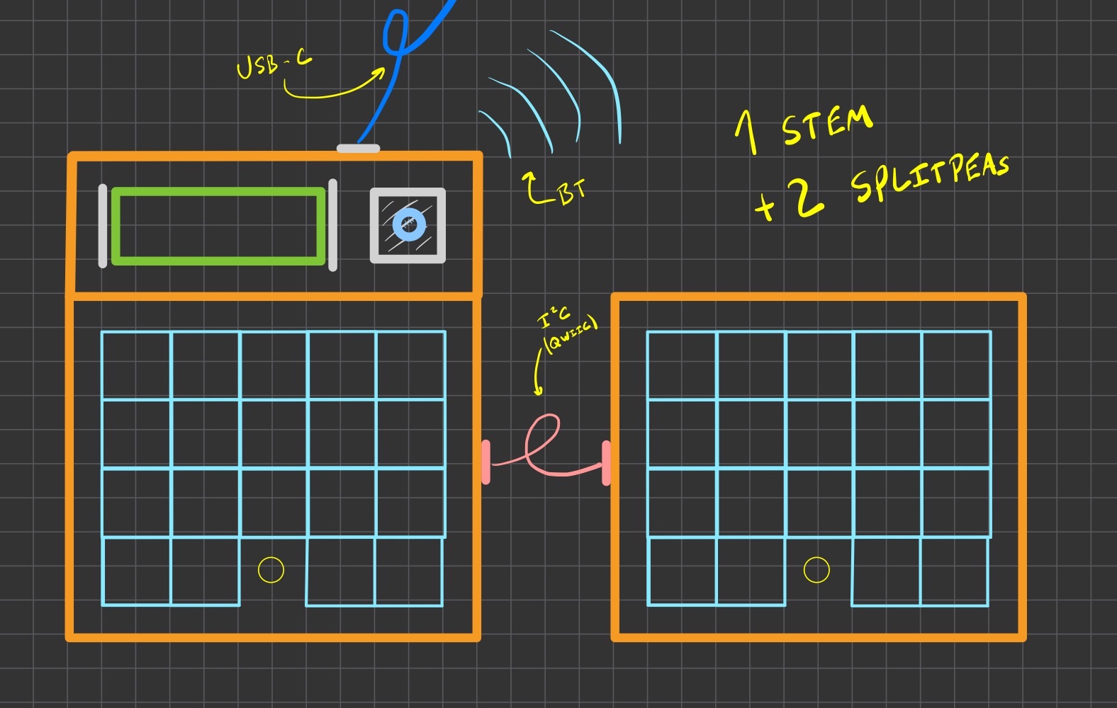
For the first keyboard, I expect to use one stem with two Splitpea Keys, in a configuration shown below:
One Stem with Two Splitpea Keys
With the 3400mAh cell, I should have a pretty ridiculous battery life, even before optimizing the firmware, or making any hardware tweaks to improve battery usage.
In the future, it might be possible to have one stem for each half of the keyboard, meaning I could go entirely wireless! That being said, I'll probably just use it as a wired keyboard using Keyberon for a while like I did with my M60 Keyboard, until I get inspired to dig into Bluetooth.
Truth be told: I over-specced the battery and power management for the stem board, as I plan to use it for some other battery-powered projects in the future. Stay tuned for some portable, extremely LED-heavy fun projects soon :)
If you're interested in checking it out, I've put the Kicad design files up on Github, though I haven't tested them yet, so you might want to hold off ordering your own! I should be receiving my boards from JLCPCB some time in early February, and I'll share more updates on this project then.
Suggestions for Future Research
We're right at the end of the "order before Chinese New Year" window, at least from JLCPCB, which means that the next revision of the Powerbus Mini will have to wait until mid-February or so, when production resumes.
That should be fine though, as I still have lots of testing that I can do with the current hardware revision, and I still have the parts to put together six more full assemblies before I absolutely need to order any more boards or parts.
I'm certainly never in a shortage of projects in progress at any given time :)
A quick request!
I'd super appreciate it if you could share this newsletter with other folks who are interested in hardware, tooling, or embedded Rust.
Sending it along in your favorite Discord or Slack channels, on Twitter or other social media, or just forwarding the email would help me out a lot!
If they are interested in subscribing (or if you had this forwarded to you), they can subscribe to the newsletter here! I also post these newsletters a week later on my blog, which has an RSS feed you can also subscribe to.
Thanks again for subscribing and following along :)