OneVariable Newsletter - 2021-12-22
2021-12-22This article was originally featured on the OneVariable Applied Research newsletter. If you'd like to get early access to these reports, you can sign up for the newsletter here. Newsletter emails are sent every Wednesday.
Articles are posted on my blog one week after appearing on the newsletter.
Abstract and Results
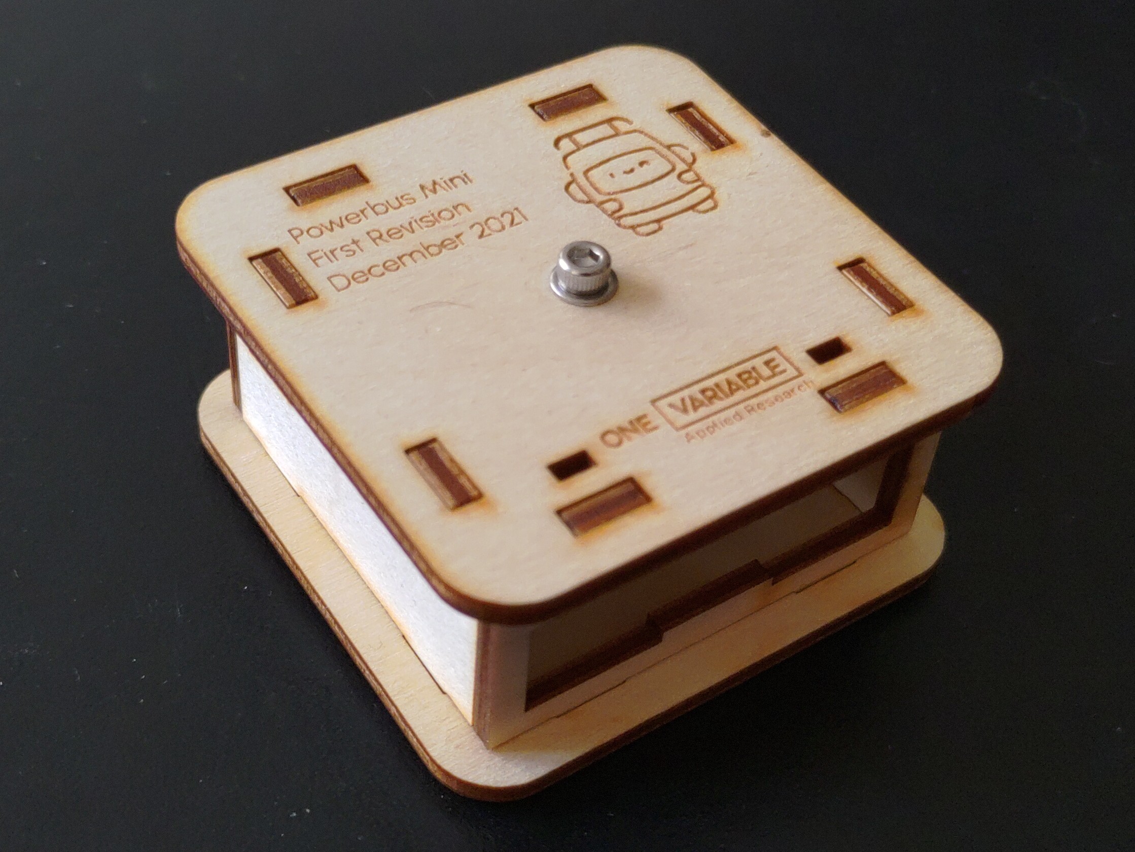
Shortly after the newsletter went out last week, I picked up the laser cut cases!
Put together, I think they look really slick!
First case, fully assembled
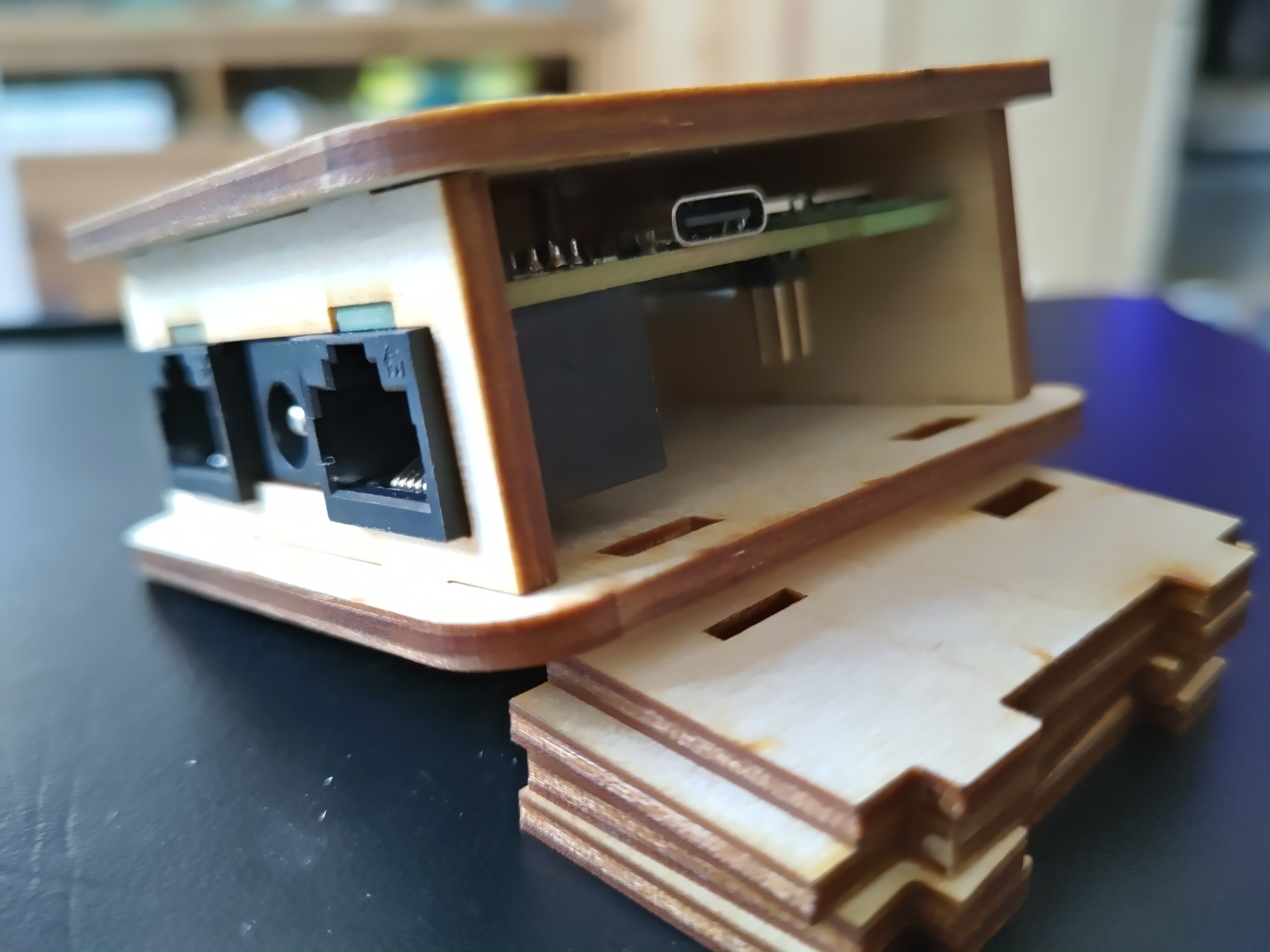
They turned out great, but I made a couple of little design errors. The biggest of which was I placed the USB-port cutout under the PCB, instead of over.
Outside of that, some of the port cutouts were a little tighter than I intended, though those were pretty quickly fixed with some sandpaper.
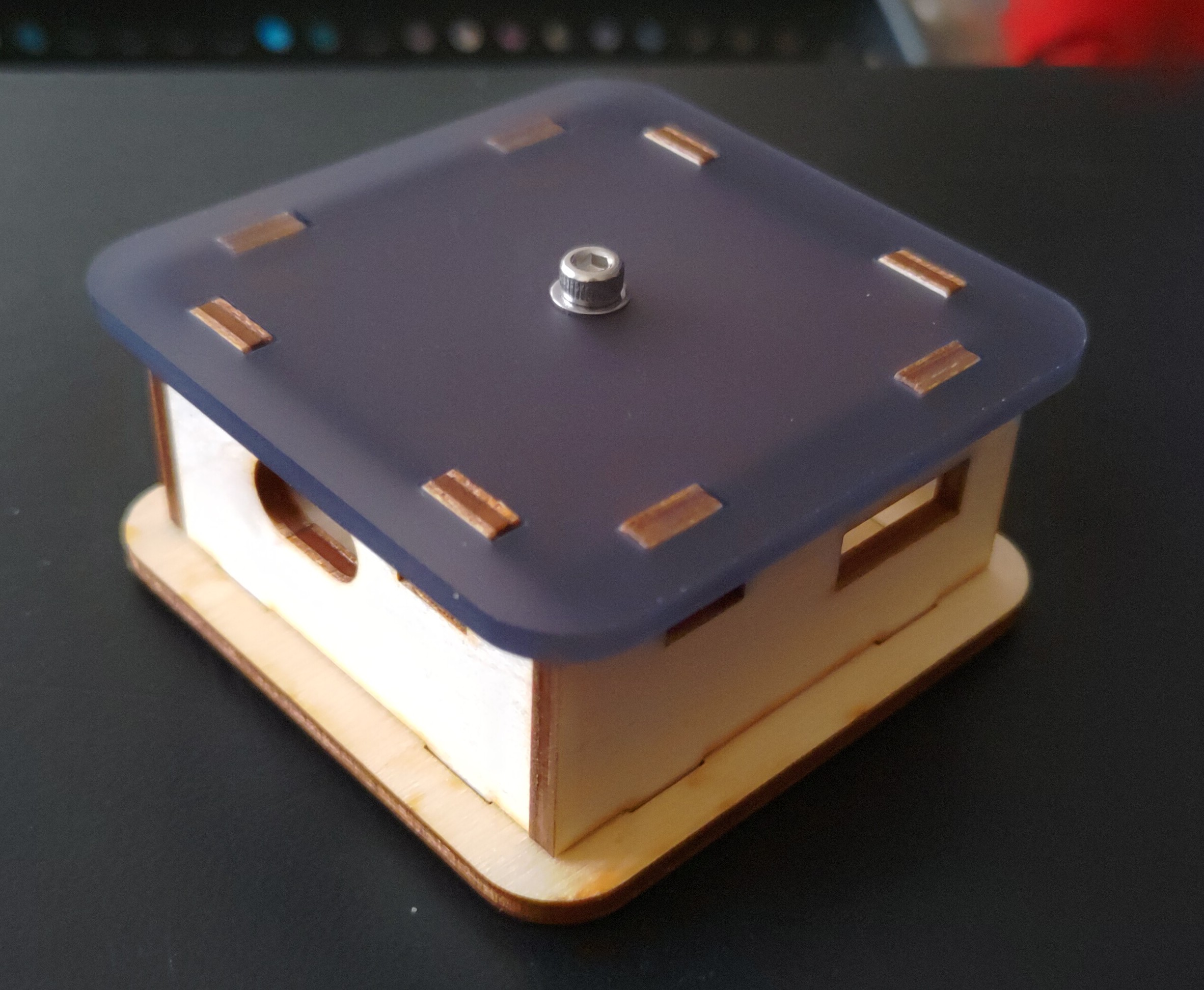
I also cut a few top layers with some of Adafruit's LED Diffusion Acrylic, which looks pretty slick with the notification LEDs.
The whole case assembly is held together with a single M3 bolt and a rivet nut, which worked out really well.
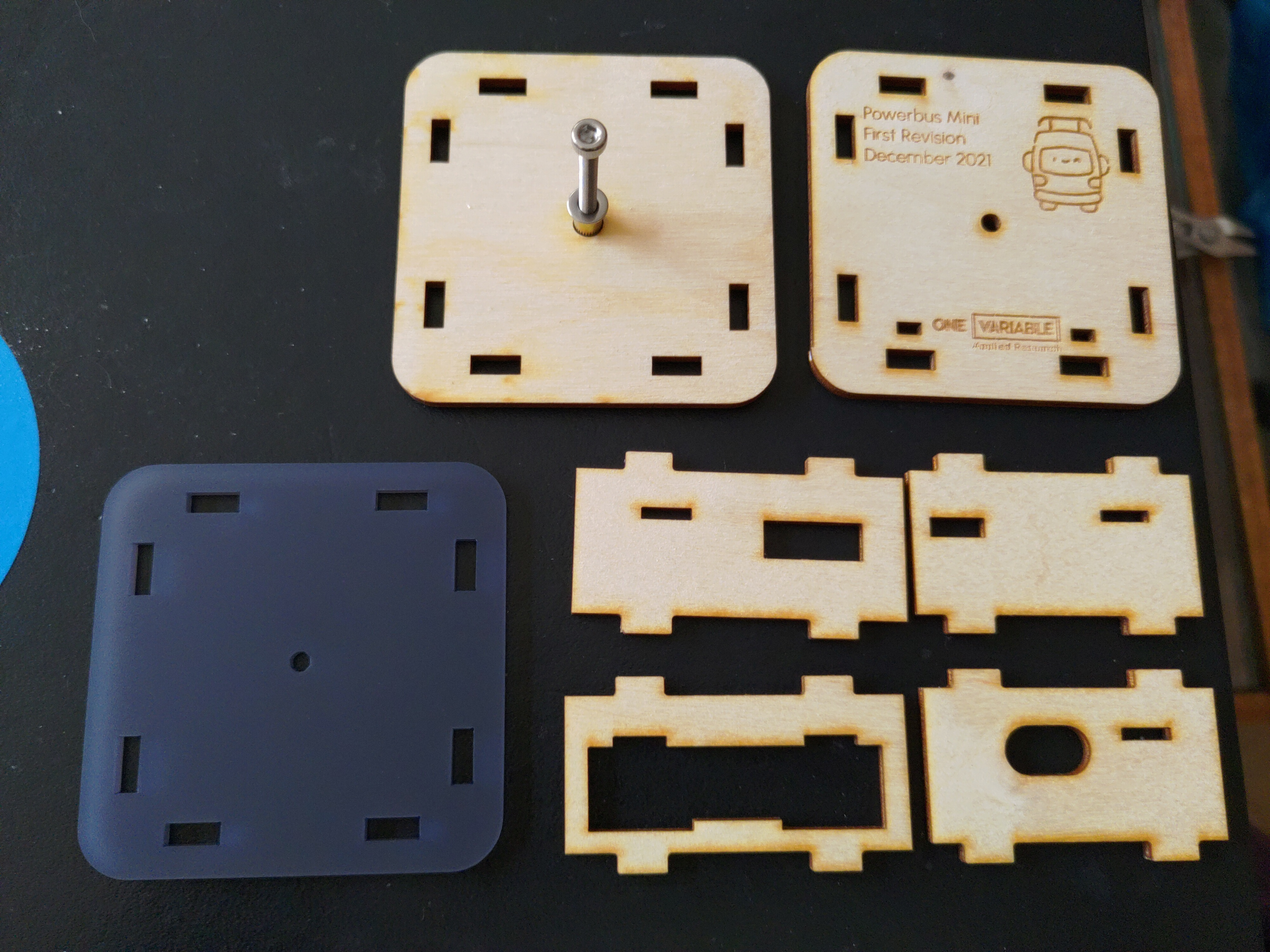
Once I build a couple of more boards, and see if there are any other changes I want or need, I'll get a few replacement parts cut for the side panels that need revision.
Board in case, minus the USB panel
On the software side, I've been chewing through software tasks, with a few highlights:
- The QSPI driver is now working
- The bootloader now supports QSPI
- The Anachro protocol now uses the
byte-slabcrate for memory mgmt - The Anachro broker is now running on the Powerbus-Mini
- USB connectivity is up and running
- Anachro-over-USB is now working
Case with Acrylic Top Layer
We're getting really close to having networking and bootloader support fully working, which means the fun parts start soon!
Background Information
One of the fun aspects of working at the driver/firmware level, is that hardware has bugs too! These are typically called "hardware errata", and when known, are listed by the manufacturer. Often, these bugs are never fixed, and require a software work-around.
Unluckily for me, I ran into two of these while writing support for the QSPI peripheral of the Nordic nRF52840!
The first, nRF52840 Errata 216, causes the CPU to halt if you read the QSPI configuration values after activating the QSPI hardware. In my boot sequence, I do roughly this:
- The bootloader starts and uses QSPI
- The bootloader disables QSPI
- The bootloader starts the application
- The application enables QSPI
In my driver, I originally used the "modify" API for changing the QSPI register settings. This causes a "read, modify, write" sequence, which triggers Errata 216! The fix for this was luckily pretty easy: I replace the "modify" with a "write", which doesn't read-back the current state first. With this patch, I was able to avoid the errata.
Definitely not a fun way to spend an evening!
Case parts, dissassembled
The second errata was a bit more odd, nRF52840 Errata 215 causes back-to-back reads of QSPI memory to sometimes read incorrect values. In the bootloader, I read firmware image header data, which includes data like the length of the firmware image, as well as a Poly1305 signature of the image for verifying validity.
Oddly enough, ONLY in "debug" mode, I was seeing a corrupted Poly1305 signature, while the calculated signature was still correct. My best guess is that release mode was combining these separate reads into a single, larger one (due to software optimizations), which avoided the errata.
In the future, I'll change these smaller reads to one combined read of the header information into RAM, instead of directly reading each field.
Suggestions for Future Research
Data Architecture Drawing
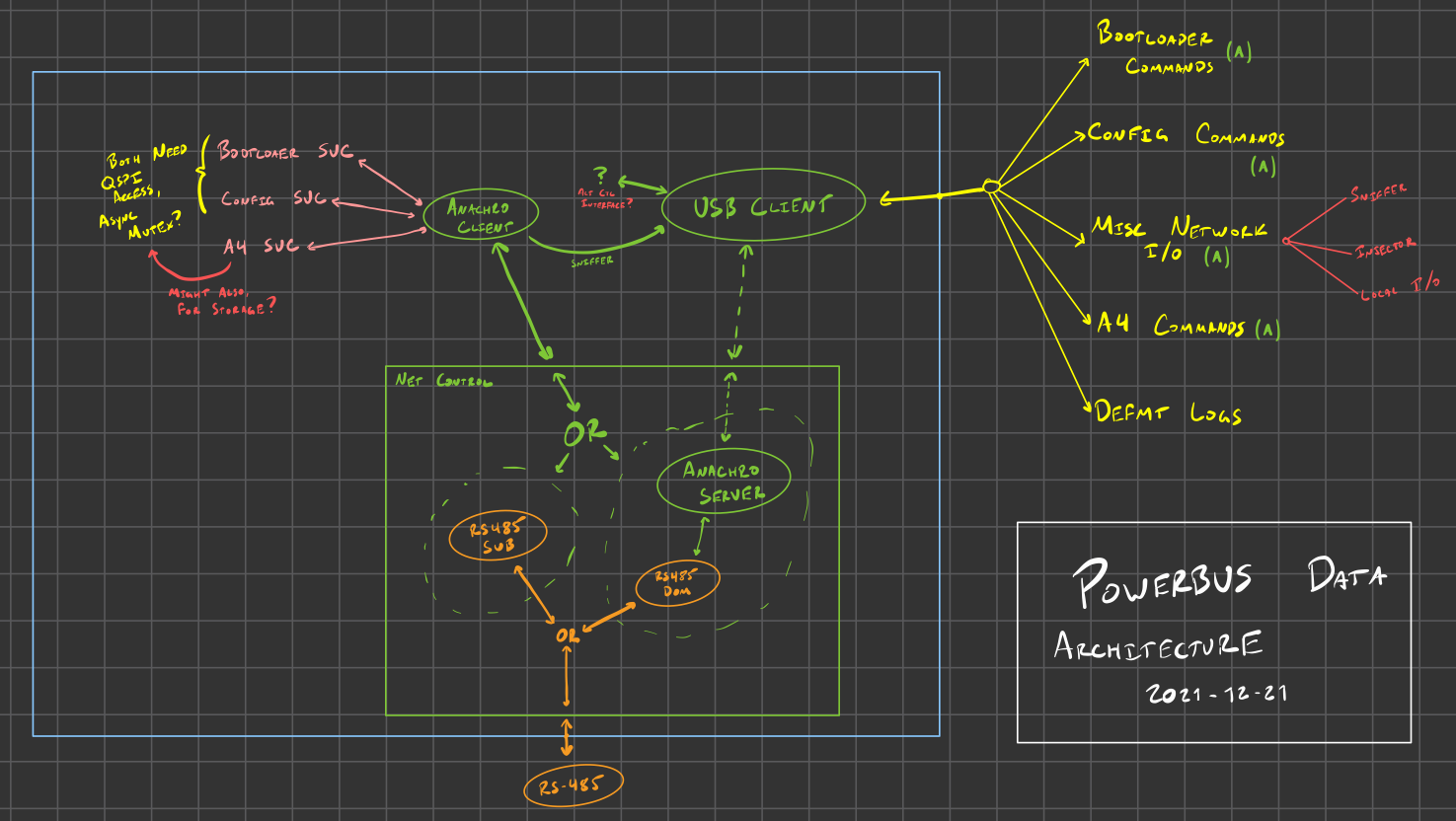
I've also been putting a lot of thought into how the data communication should work for the Powerbus Mini, particularly with regard to communicating over USB and RS-485.
Since the server/broker role in the Anachro protocol is handled by an embedded device, I plan to have the PC connected over USB to just connect to the broker using USB-Serial as a transport, instead of RS-485. This allows the USB to act as a "bridged network interface", which means that the PC is just connected to the network, and every other node can talk with it "natively" using the Anachro protocol.
I plan to support the bootloading protocol as well as defmt logging over regular Anachro protocol messages. This limits the number of special protocols and interfaces I will need to build, and should be sufficient for now, at least.
I already have a PC binary that is able to connect to the Anachro broker over USB, which means that the majority of the remaining work is plumbing the bootloader and logging services into the Anachro protocol, and writing a PC-side binary that can trigger updates, or process logging messages.
The next immediate step is to get this all working with just the single USB client. After that, I'll need to finish connecting the RS-485 protocol into Anachro, so I can manage more than one device at a time.
Stay tuned for more progress next week!
A quick request!
I'd super appreciate it if you could share this newsletter with other folks who are interested in hardware, tooling, or embedded Rust.
Sending it along in your favorite Discord or Slack channels, on Twitter or other social media, or just forwarding the email would help me out a lot!
If they are interested in subscribing (or if you had this forwarded to you), they can subscribe to the newsletter here! I also post these newsletters a week later on my blog, which has an RSS feed you can also subscribe to.
Thanks again for subscribing and following along :)